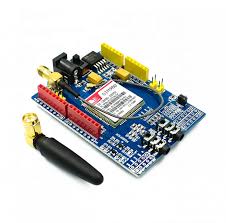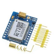
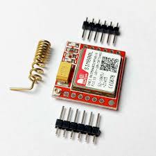
Mini A6 GA6-B GPRS GSM Module Board COM56, R24
This is mini version serial GSM / GPRS core development board based on GPRS A6 module. It supports dual-band GSM/GPRS network, available for GPRS and SMS message data remote transmission.
The board features compact size and low current consumption. With power saving technique, the current consumption is as low as 3mA in sleep mode.
It communicates with microcontroller via UART port, supports command including GSM 07.07, GSM 07.05 and Ai-Thinker enhanced AT Commands.
Specifications
Current 2A (Max)
Frequency 850 / 900 / 1800 / 1900MHZ
Length x Width x Height 22.8mm x 16.8mm x 2.2mm
Operating Voltage 4.5V ~ 5.2V
Speed GPRS data features, data rates Download 85.6Kbps, upload 42.8Kbps
Temperature Range -30℃ – +80℃
How to get started with Mini A6 GA6-B GPRS GSM Module Board
A6 GA6-B GSM/GPRS module is a miniature GSM modem, which can be integrated into a great number of IoT projects. You can use this module to accomplish almost anything a normal cell phone can; SMS text messages, Make or receive phone calls, connecting to internet through GPRS, TCP/IP, and more! To top it off, the module supports quad-band GSM/GPRS network, meaning it works pretty much anywhere in the world.
Wiring – Connecting A6 GA6-B GSM module to Arduino UNO
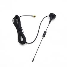
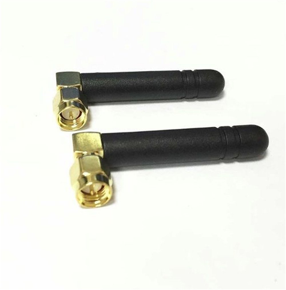
We can begin hooking it up to our Arduino! To start with, connect U_TxD and U_RxD pin on module to digital pin#2 and #4 on Arduino as we’ll be using software serial to talk to the module. Connect VCC pin on module to 5v VCC pin on Arduino.Connect GND pin on module to GND pin on Arduino Finally, connect the antenna, insert fully activated Micro SIM card in the socket.
Arduino uno A6_mini GA6-B GSM
5V VCC
GND G
D2 U_TX
D4 U_RX
Arduino Code – Testing AT Commands
For sending AT commands and communicating with the Mini A6 GA6-B module, we will use the serial monitor. The sketch below will enable the Arduino to communicate with the A6 Mini A6 GA6-B module on serial monitor. Before we proceed with detailed breakdown of code, connect your Arduino to PC, compile below code and upload it to the Arduino.
Once you open a serial monitor, make sure that ‘Both NL & CR’ option is selected!
#include//Create software serial object to communicate with A6 SoftwareSerial mySerial(2, 4); //A6 Tx & Rx is connected to Arduino #2 & #4 void setup() { //Begin serial communication with Arduino and Arduino IDE (Serial Monitor) Serial.begin(115200); //Begin serial communication with Arduino and A6 mySerial.begin(115200); Serial.println("Initializing..."); delay(1000); mySerial.println("AT"); //Once the handshake test is successful, it will back to OK updateSerial(); mySerial.println("AT+CSQ"); //Signal quality test, value range is 0-31 , 31 is the best updateSerial(); mySerial.println("AT+CCID"); //Read SIM information to confirm whether the SIM is plugged updateSerial(); mySerial.println("AT+CREG?"); //Check whether it has registered in the network updateSerial(); } void loop() { updateSerial(); } void updateSerial() { delay(500); while (Serial.available()) { mySerial.write(Serial.read());//Forward what Serial received to Software Serial Port } while(mySerial.available()) { Serial.write(mySerial.read());//Forward what Software Serial received to Serial Port }
Frw 12,500





.jpeg)
