How to Detect the Direction of Sound Using Arduino?
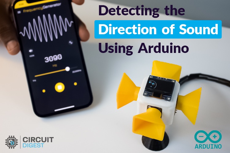
 Detect the Direction of Sound Using Arduino
Sound direction detection is a fascinating concept in robotics and automation. It allows a device to "hear" and determine the direction of a sound. This concept has numerous applications, including robot navigation, smart security systems, gaming, and entertainment. Earlier we showed you how to measure sound in dB using Arduino, in this tutorial let's learn how to find the direction of sound using Arduino and a few microphones.
Above, you can see a short demonstration GIF of the project we’ll be discussing today. Let's learn some basics about detecting sound direction using Arduino and a few microphones. Without further ado, let’s dive into the technique used here.
How does Sound Localization works?
In a nutshell, sound localization involves detecting sound from four microphones simultaneously, identifying the highest amplitude signal, and determining the direction of the sound source based on the microphone receiving the strongest signal. While this method is straightforward, it has limitations that may reduce system efficiency.
This is where an advanced method, Fast Fourier Transform (FFT) analysis, comes into play. FFT shifts the time-domain signal to the frequency domain, making it easier to differentiate sounds—like human voices versus background noise—by analyzing frequency ranges. This approach reduces some limitations of the simpler method and enables detection within a fixed range of frequencies.
Using four microphones positioned around the device, the system listens for a target frequency (e.g., 3000 Hz) and compares the magnitude of sound from each microphone. The Arduino processes the signals in real-time, finding the direction based on the strongest signal. This information is then visualized on an OLED screen with animated "eyes" that track the sound source. This physical setup is essential to accurately identify the direction, allowing detection over a full 360°.
 You don't need to rely on 3D printing for this setup; simple cardboard or foam can do the job well.
Now that you understand the concept, let’s build it!
3D Model
I designed a 3D case for this project using TinkerCad, which should be easy to replicate. The 3D model is available on GitHub, with a link provided at the bottom of this document.
 Note: 3D printing is not necessary to demonstrate sound localization. Alternatives like foam, cardboard, or small boxes can be used.
Components Required
Below is the list of required components. This project has been tested with Arduino UNO R4 WiFi, Arduino UNO R3, and ESP32, so you can use any of these. However, there may be minor code adjustments for each microcontroller.
- Arduino UNO R4 WiFi - 1
- MAX4466 Microphone Amplifier Module - 4
- 0.96” OLED Display (128x64 px) - 1
- Connecting wires - Required
- BreadBoard - Optional
- 3D Printing - Optional
Circuit Diagram
The circuit diagram depends on your choice of microcontroller. For Arduino UNO, the circuit is similar to the one shown below.
 When using a different microcontroller, focus on selecting suitable ADC pins for microphone inputs. For Arduino, I used A0, A1, A2, and A3 for microphone inputs, with A4 and A5 as SDA and SCL pins for the OLED display.
For simplicity, I powered all microphones and the OLED display with the Arduino’s 3.3V output. The MAX4466 module supports input voltages from 2.4 to 5.5V, and the OLED operates at 3.3V (some displays may support up to 5V, but I suggest 3.3V for safety).
With the circuit clear, let’s move on to the assembly.
Hardware Assembling
Let’s begin assembling the hardware. Starting with the head section, place all components as shown.
 I secured the microphone module and OLED display with hot glue and shortened the pins for hassle-free soldering. You can choose the method that suits you best.
I wrapped a bit of tape around the microphones to ensure a snug fit.
I started by soldering the OLED display, creating a parallel connection for the power rails, with individual connections for the analog output and the SDA/SCL pins.
 You can see the partial wiring above, followed by the complete wiring. I used multicolor ribbon cables to simplify things.
 After completing the soldering, I routed the wires through the center hole in the bottom 3D print, which functions like a hollow pipe. I then soldered header pins to connect easily to the Arduino UNO.
With the hardware assembly complete, let’s move on to coding.
Coding Part
Now, let’s break down the code logic and functionality for this sound localization project.
The program detects the direction of sound using four microphones, performing an FFT to analyze sound frequencies, particularly around 3000 Hz. Based on sound direction, it displays "eyes" on an OLED screen to track the source. If no sound is detected, it shows "sleepy eyes" as an idle state.
Now lets breakdown the code, starting from the utilized libraries.
Libraries Used:
- arduinoFFT - Available in Library Manager
- Wire - default library
- Adafruit_GFX - Available in Library Manager
- Adafruit_SSD1306 - Available in Library Manager
These libraries are compatible with both Arduino UNO and ESP32.
 Next, constants, variables, and libraries are initialized. I created separate FFT objects for each microphone to manage them independently. Important control parameters, such as target frequency, magnitude threshold, and sampling frequency, are defined. You can adjust these to fine-tune the system.
And next, you can see some user defined functions in our programe.
 Code Flow:
Setup Function (setup()):
- Initializes the serial communication and the OLED display.
- Clears the display to ensure it's ready to show graphics.
Main Loop (loop()):
- The loop() runs continuously, calling the function determineAngle() to check where the sound is coming from.
- It then calls drawEyes() to update the OLED display with either normal or sleepy eyes, depending on the sound data.
Determining the Sound Direction (determineAngle()):
- Takes 64 samples from each microphone and applies FFT to convert the sound data into frequency data.
- It checks the magnitude of the target frequency (3000 Hz) from each microphone and determines which microphone has the strongest sound signal.
- Based on the strongest signal, it calculates the angle of the sound (0°, 90°, 180°, or 270°).
Displaying the Eyes (drawEyes()):
- The drawEyes() function draws different eye graphics on the OLED screen based on the calculated angle.
- If the sound stays the same for a long period (based on the angleCounter(), it will display sleepy eyes.
Now hope you understand the working logic of our code. You can find the complete code at the bottom of this document.
Next lets see the working of the program in detail.
Working of the Sound localization project
Once the program is uploaded, the final result can be seen in the GIF below. We tested it with various target frequencies, and it responded accurately.
As per the current code, if the sound is coming from same direction for long time the OLED show the sleep Symbol.
This project can be further expanded to detect a range of frequencies rather than a specific one. However, it’s still susceptible to noise. While software solutions can help, hardware solutions like analog noise filters on microphone inputs will yield the best results.
Applications of Sound Direction Detection Project
- Robotics Navigation: Robots equipped with sound localization can detect the direction of voice commands or nearby sounds, helping them interact more naturally with people or respond quickly to alerts.
- Smart Security Systems: By integrating sound direction detection, smart security systems can identify suspicious sounds—like breaking glass or loud disturbances—and immediately focus cameras or alarms in that direction.
- Interactive Art Installations: Artists and designers can use sound direction detection to create immersive exhibits that respond to audience sounds, allowing installations to come to life based on visitor interactions.
- Voice-Activated Systems: In smart home devices, sound direction detection helps microphones focus on the source of voice commands, improving accuracy and responsiveness for virtual assistants like Alexa or Google Home.
- Environmental Monitoring: This technology can assist in wildlife monitoring by pinpointing the direction of animal calls or other environmental sounds, aiding in research and conservation.
- Acoustic Measurements and Sound Profiling: Engineers and researchers can use this system to study how sound travels in different environments or to conduct precise measurements of sound direction in experiments.
Components Required
- Arduino UNO R4 WiFi
- 1 MAX4466 Microphone Amplifier Module
- 4 0.96” OLED Display (128x64 px)
- 1 Connecting wires
- Required BreadBoard
- 3D Printing
For More Information
+250783159293

